



View our installation instructions for installing the 5th wheel to the goose pin box, installing the Gooseneck air hitch & coupler, along with setting your air pressure. When used & set up properly, the Gooseneck surge air hitch will make noticeable improvements in your gooseneck trailer towing quality. Giving both the truck and 5th wheel camper trailer a smoother ride with less trailer fatigue and breakage. We want you to have the best possible towing experience with your product, and proper installation is important. If you need help, we are here for you. Just give us a call at 701-707-2666 or use our contact us form. You can also look up the item’s product page on our website and view the installation tab. Most products on our website have a setup guide and installation video.
Installing Shocker Quick Air 5th Wheel to Gooseneck Hitch Video
Quick Air 5th Wheel to Gooseneck Air Pressure Settings
Download Quick Air 5th Wheel to Gooseneck Installation Manuals
- Quick Air 5th to Goose Conversion Installation Instructions
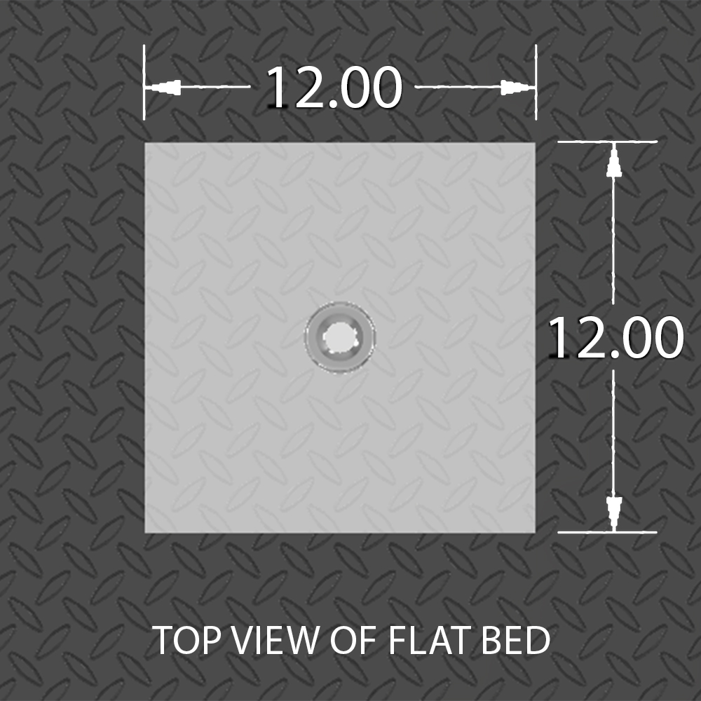
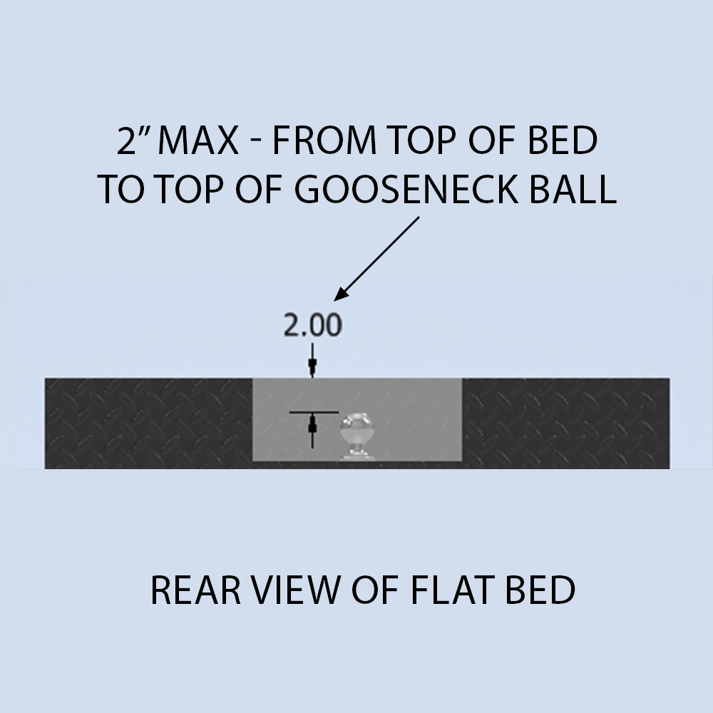
- Flatbed Recessed Gooseneck Ball Fitment Guide
Maximum Weight Rating For Quick Air 5th To Gooseneck Pin Box
Safety Notice: Towing capacity is limited by its lowest rated component. DO NOT exceed Gross Vehicle Weight Rating or Shocker Hitch weight ratings. The Quick Air Pin Box is rated for 24,000 lbs GTW and 6,000 lbs TW. Any modification to the hitch or pin box voids the warranty and is done at your own risk. Manufactured at Shocker Hitch USA in Jamestown, ND.
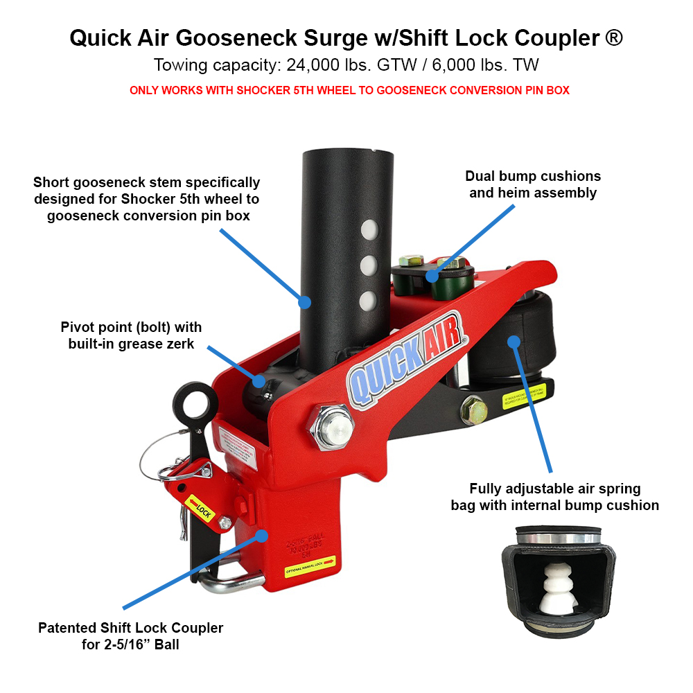
This gooseneck stem and coupler has a shorter stem than a normal gooseneck and is designed to be used with the Shocker Replacement Gooseneck Pin Box for 5th Wheel Campers only. This gooseneck air hitch cannot be used on a normal gooseneck trailer as the inner tube steel is too short for that application.
Installation – Quick Air Pin Box (SH-RVGC-4405 | SH-RVGC-4410 | SH-RVGC-4415)
Tools Required: Impact Driver with 15/16″ Socket | 15/16″ Wrench
Step 1: Existing Pin Box Removal
- Level Surface: Ensure the vehicle and the trailer are parked on a level surface.
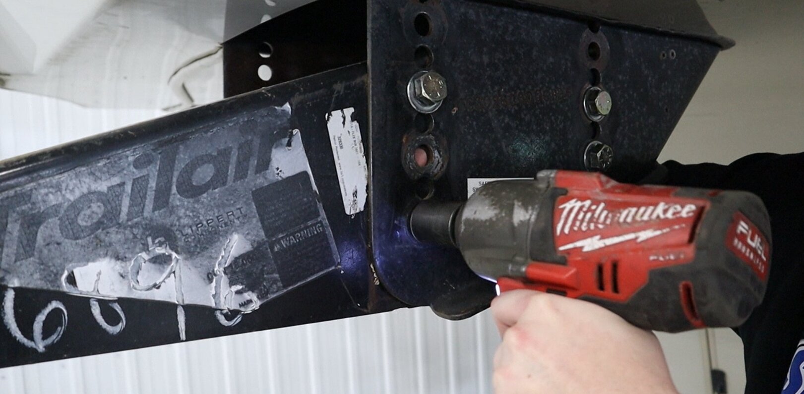
- Unbolting: Remove the bolts from the existing pin box on the camper/trailer in a star-like pattern using an impact driver with a 15/16″ socket on the bolt head and a 15/16″ wrench on the nut (Figure 1).
- Remove Existing Pin Box: With assistance, remove the existing pin box from the camper/trailer.
Step 2: Install Quick Air Pin Box
- Lubricate: It is recommended to use spray grease/lubricant on the pin box bracket to help with installation.
- Insert and Align: With assistance, slide the Quick Air Pin Box into the camper/trailer pin box bracket. Align the holes of the pin box bracket with the holes on the Quick Air Pin Box.
- Add Hardware: Using the existing hardware from the original pin box, insert all bolts and washers from the outside of the bracket into the holes of the Quick Air Pin Box.
Step 3: Tighten and Torque:
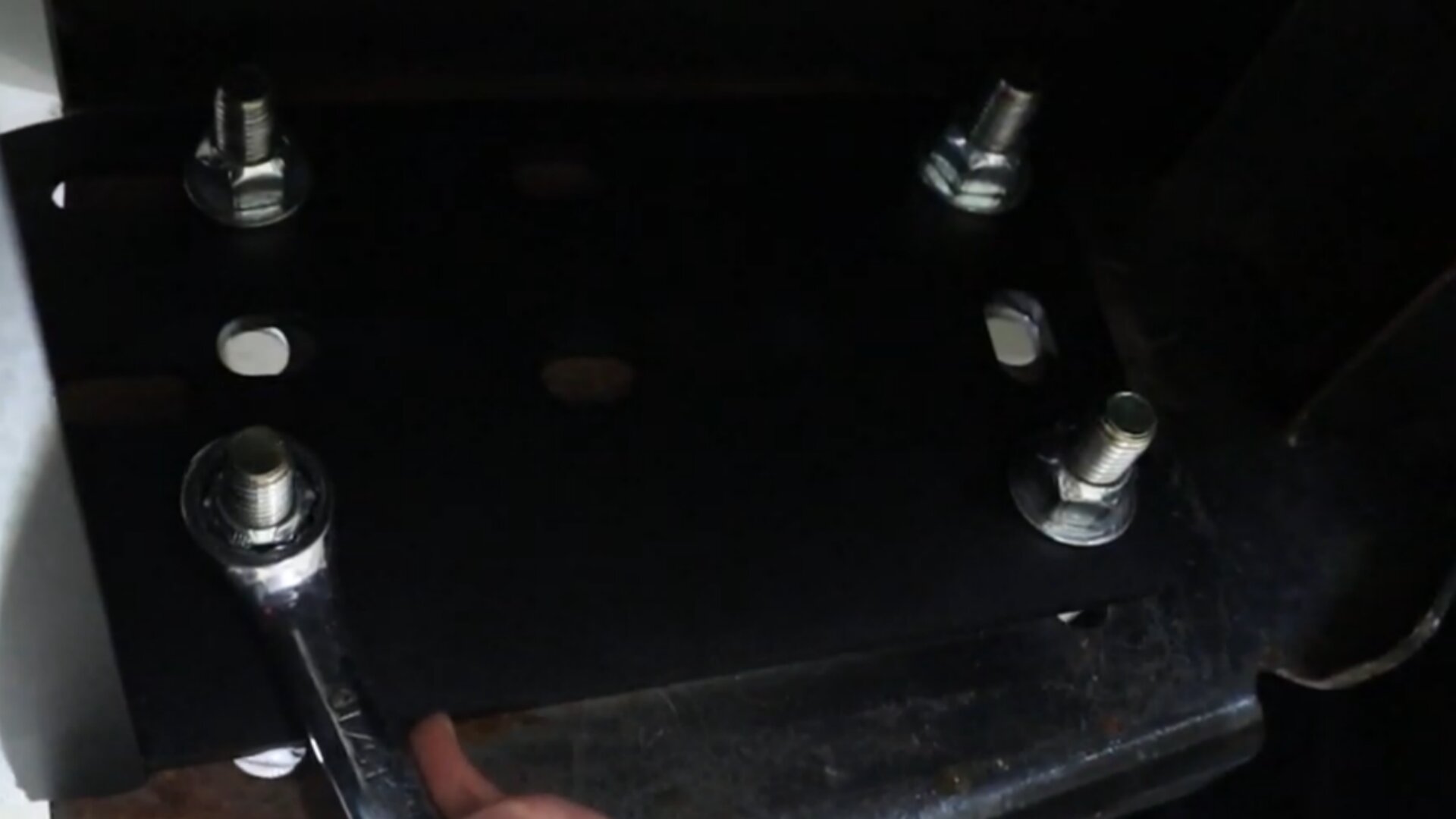
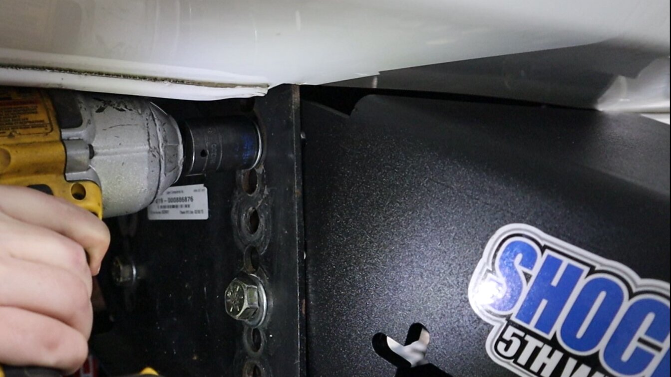
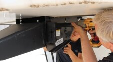
- Tighten: Use an impact driver with a 15/16″ socket on the bolt head and a 15/16″ wrench on the nut and tighten the bolts (Figures 2 & 3).
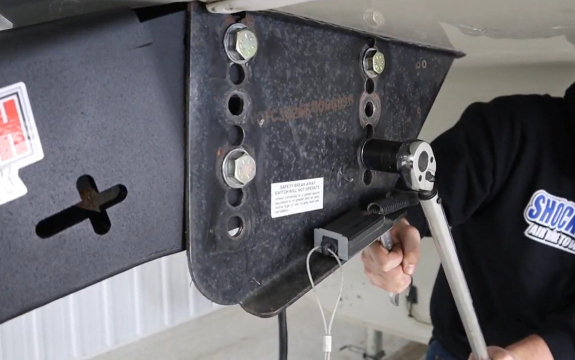
- Torque: Torque the bolts to 120 ft-lbs using a torque wrench (or refer to trailer manufacturer specifications) (Figure 4).
- Important: DO NOT overtighten bolts as this can lead to premature wear and potential failure of the pin box. It is recommended to use additional washers inside the pin box to reduce wear.
Installation – Quick Air Gooseneck Surge (4RND-STR-SL-CA | 4RND-STR-DEM-CA)
Tools Required: 1-1/8″ Wrench | 3/4″ Wrench | Air Compressor
Step 1: Installing Gooseneck Surge
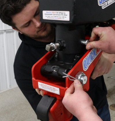
- Insert Hitch: With assistance, insert the stem on the Gooseneck Surge into the outer tube on the Quick Air Pin Box (Figure 5).
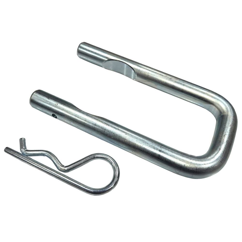
- Align and Pin: Insert the 3/4″ gooseneck pin through the desired hole and secure using a cotter pin clip.
Step 2: Measuring and Adjustment
- 1st Measurement: Take a measurement from the bed of your vehicle to the ground and record the measurement.
- 2nd Measurement: Measure from the bottom of the Quick Air Gooseneck Surge coupler to the ground.
- Adjustment: Adjust the height of the Quick Air Gooseneck Surge to match the 1st Measurement.
Step 3: Orientation and Alignment
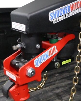
- Air Spring Bag Orientation: For the Quick Air Gooseneck Surge, the air spring bag must face the rear towards the trailer (Figure 6).
- Verify Alignment: DO NOT tow if the hitch is crooked; ensure the hitch is straight and parallel with the trailer.
- Correction: If the hitch is crooked, readjust at the stem or trailer pin.
- Tighten Set Bolt: Using a 3/4″ wrench, tighten the set bolt on the trailer to lock the hitch into place. Then, tighten the jam nut using a 1-1/8″ wrench.
Installation – Gooseneck Stem & Coupler (SL-4RND-STR-CA | DEM-4RND-STR-CA)
Tools Required: 1-1/8″ Wrench | 3/4″ Wrench
Step 1: Installing Gooseneck Stem & Coupler
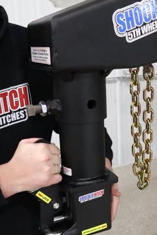
- Insert Hitch: With assistance, insert the stem into the outer tube of the trailer (Figure 7).
- Align and Pin: Insert the 3/4″ gooseneck pin through the desired hole and secure using a cotter pin clip.
Step 2: Measuring and Adjustment
- 1st Measurement: Take a measurement from the bed of your vehicle to the ground and record the measurement.
- 2nd Measurement: Measure from the bottom of the Gooseneck Coupler to the ground.
- Adjustment: Adjust the height of the Gooseneck Stem & Coupler to match the 1st Measurement.
Step 3: Orientation and Final Tightening
- Orientation: The Stem & Coupler can be installed with the latch facing either the cab or the trailer. Orientation does not matter (Figure 8).
- Tighten Set Bolt: Using a 3/4″ wrench, tighten the set bolt on the trailer to lock the hitch into place. Then, tighten the jam nut using a 1-1/8″ wrench.
Installation – Safety Chain Kit
Always Use Safety Chains With Goosenecks As It’s Required By Law
Tools Required: Impact Driver with 3/4″ Socket | 3/4″ Wrench
New Version Gooseneck Pin Box (2024-Newer):
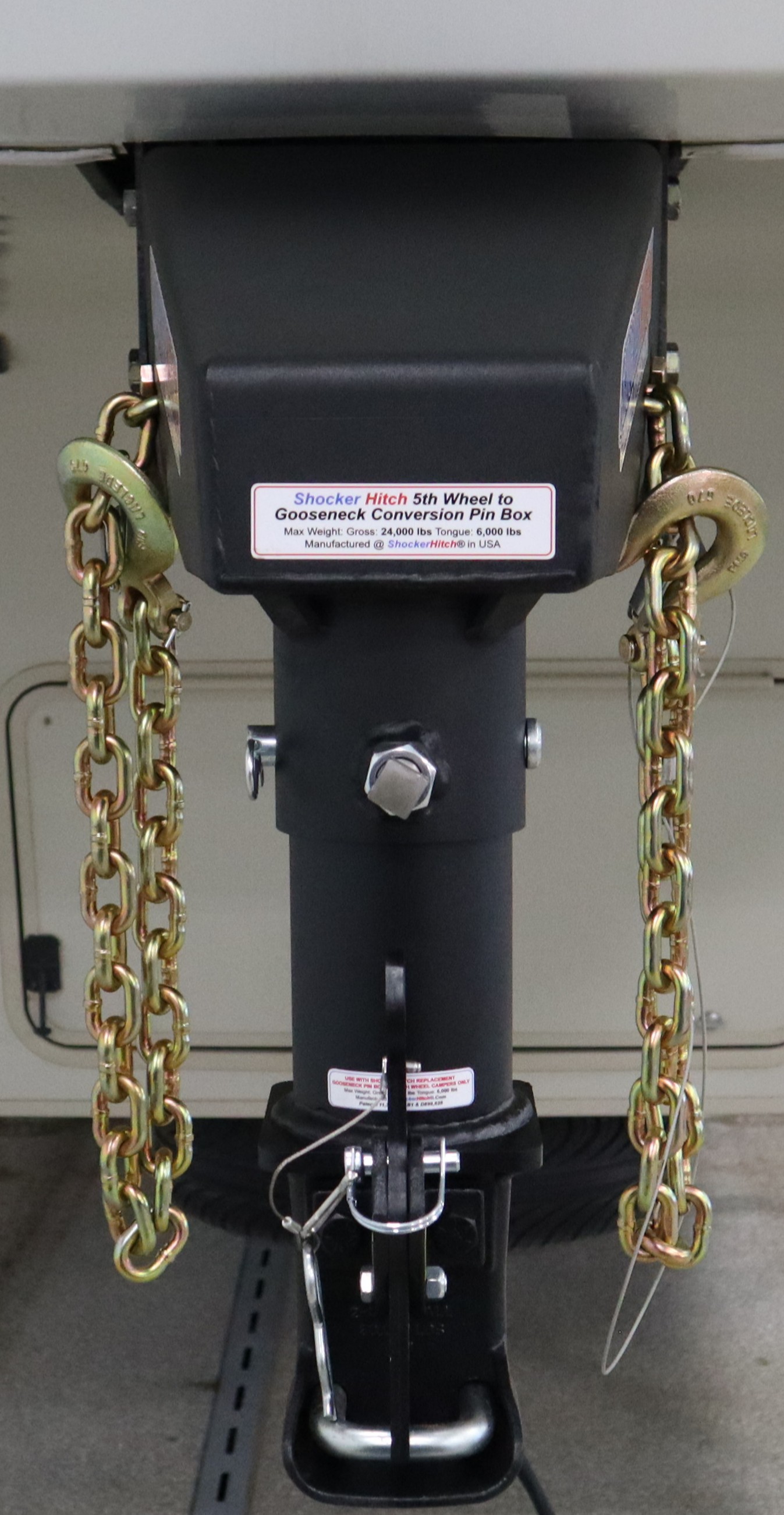
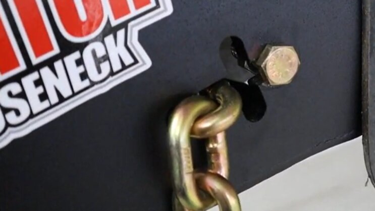
- Feed Chain: Take the open end of the chain and feed it through the cross-cutout on the Quick Air Pin Box to the desired length (chains should not be tight; maintain a loose fit).
Step 2: Install and Tighten Hardware
- Add Hardware: Insert the provided 1/2″ bolt through the short section of the cross, and hand thread a nut onto the protruding end of the bolt on the inside of the Quick Air Pin Box.
- Tighten: Use an impact wrench with a 3/4″ socket on the bolt head and a 3/4″ wrench on the nut and tighten bolts (Figure 9).
Old Version Gooseneck Pin Box (2023-Older):
Step 1: Install Chain Brackets
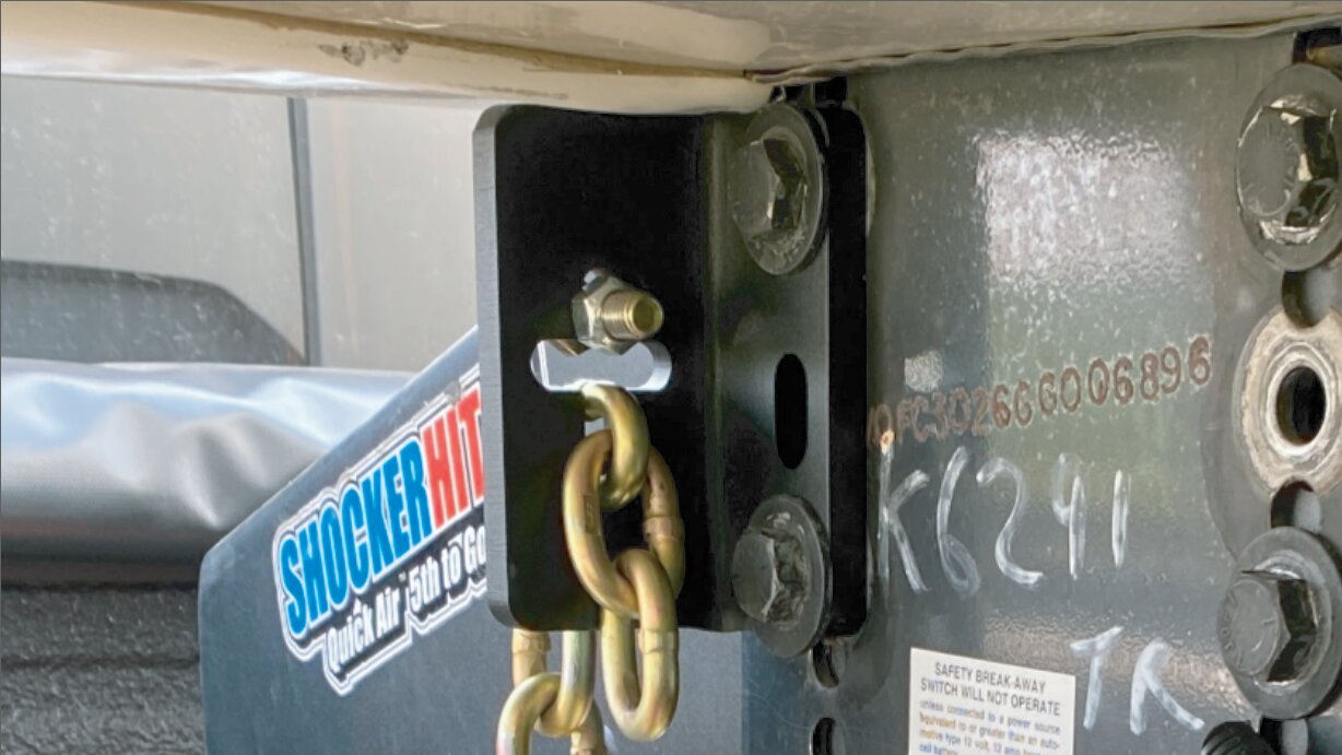
- Bracket Installation: Before putting on your Quick Air Pin Box, install the Chain Bracket on the top two holes on either side that the Quick Air Pin Box will fit into and use existing hardware to install the bracket (Figure 10).
- Feed Chain: Take the open end of the chain and feed it through the cross-cutout on the Quick Air Pin Box to the desired length (chains should not be tight; maintain a loose fit so they do not bind or stretch during a right or left turn).
Step 2: Install and Tighten Hardware:
- Add Hardware: Insert the provided 1/2″ x 1-1/2″ bolt through the short section of the cross, and hand thread the provided 1/2″ nut onto the protruding end of the bolt on the inside of the Quick Air Pin Box. Do this for both sides.
- Tighten: Use an impact wrench with a 3/4″ socket on the bolt head and a 3/4″ wrench on the nut and tighten bolts (Figure 11).
Safety Notice: Safety Chain kit is rated for 24,000lbs. DO NOT exceed the maximum weight, as it can damage the safety chains or the Shocker Hitch. Ensure chains are Grade 70 transport NACM V-19.
Safety Chain Hook-Up (Old and New Versions)
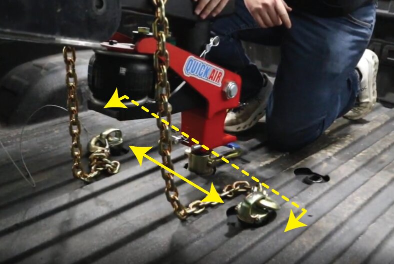
Ideal Location: The best safety chain hook-up location is slightly rearward of the ball centerline and 6″ to 12″ left or right of the ball laterally. Safety chain hook-up should not be directly in line with the ball and NEVER attached forward of the gooseneck ball (Figure 12).
Safety Notice: Do not cross the chains, as this can lead to binding of the pin box.
How To Use Shift Lock Coupler For 2-5/16″ Gooseneck Ball
To Connect:
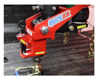
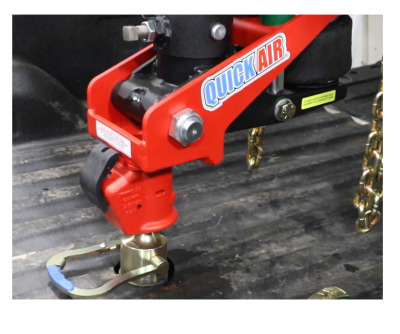
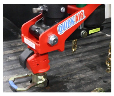
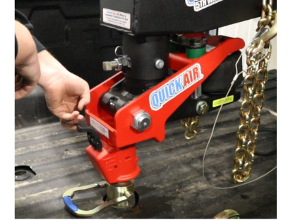
- Move the Shift Lock Handle to the unlocked position (Figure 13).
- Lower the trailer onto the gooseneck ball (Figure 14).
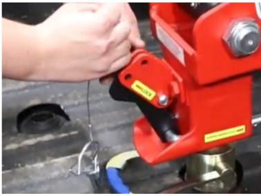
- Move the handle to the locked position and insert the quick clip pin.
Check Lock:
- U-Bolt must stick out approximately 1″ from the coupler rear when locked (Figure 15).
Manual Option:
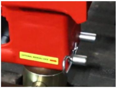
- If the handle is damaged, use the manual lock pin on the driver’s side of the U-Bolt (Figure 16).

How To Use Demco Coupler For 2-5/16″ Gooseneck Ball
To Connect:
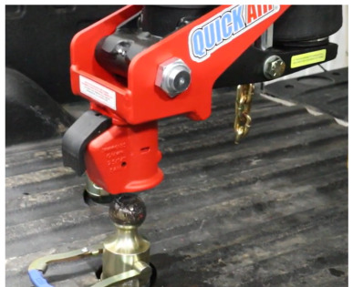
- The Demco EZ-Latch is a self-latching system. Lower the coupler onto the ball until the latch snaps into the locked position (Figures 17-19).
To Release:
- Pull the Demco EZ-Latch handle up and forward to release the ball (Figure 20).
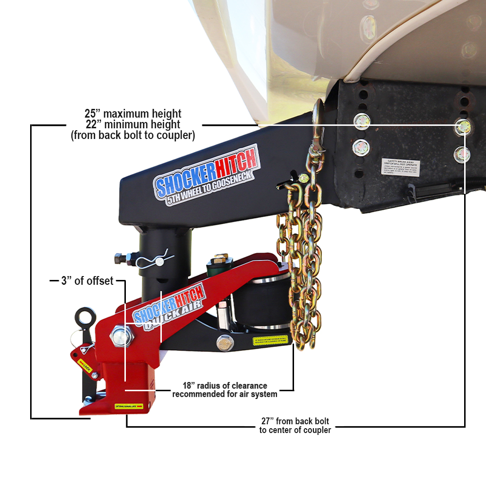
Additional Info: Clearance For Air Spring Bag & Recessed Flat Bed Pickups | Diagrams
How To Use
Step 1: Hook Up Trailer
- Lowering Trailer: Lower your trailer onto the gooseneck ball and lock the coupler into place (See coupler-specific instructions for “How To Use Shift Lock Coupler For 2-5/16″ Gooseneck Ball” or “How To Use Demco Coupler For 2-5/16″ Gooseneck Ball” models above).
- Safety Chains: Securely hook your safety chains to the anchor point in the bed of the truck (See “Safety Chain Hook-Up (Old and New Versions)” section above).
- 7-Way Plug: Plug your trailer’s electrical cord into the socket in the truck bed to enable lights and brakes.
Step 2: Setting Air Pressure
- Fill Air Spring Bag: After loading your trailer, fill your hitch’s air spring bag starting at 15 PSI (Ensure bump cushions are compressed).
- Adjustment: Test drive and adjust in 5 PSI increments until optimal ride quality is reached.
- Note: When towing trailers with high wind resistance, it may be necessary to increase air pressure in the air spring bag. NEVER EXCEED 100 PSI, as this will damage the air spring bag.
- Important: When weight is added or removed, it can shift more weight to the tongue or to the rear of the trailer. Always try to keep your load distributed evenly on the trailer with the majority of the weight over the tires. When adjusting weight, always adjust your air pressure for the best ride.
Routine Maintenance Schedule
Step 1: Lubrication Schedule
- Hitch Ball & Coupler: Lubricate the coupler, Shift Lock U-Bolt, and gooseneck ball before every hook-up to prevent friction wear. Clean your hitch ball after each use to reduce wear and improve coupler lifespan.
- Main Pivot Bolt: Apply grease to the Pivot Bolt via the grease zerk located at the base of the stem.
- Stem Threads (Crank Models): For crank handle models, ensure the stem threads stay generously greased for easy adjustment.
- Frequency: It is recommended to grease all points every 2-3 months, or more frequently with heavy use.
Step 2: Hardware & Air System Inspection
- Torque Check: Periodically verify that all trailer set bolts are torqued to your trailer manufacturer’s specifications.
- Air Spring Bag Integrity: Inspect the air spring bag for any debris or rubbing.
- Coupler Pin: Ensure the safety snapper pin is in good condition and always used during transit.
Pre-Tow Checklist ✅
Hitch & Coupler Safety:
- Coupler Engaged: Ensure trailer is fully lowered onto the ball and the coupler is locked.
- Stem Hardware Tight: Confirm the set bolts on the trailer are securely tightened and the jam nut is locked down. Confirm the gooseneck through pin is secure with cotter pin clip.
- Alignment Check: Visually verify the hitch is straight and parallel with the trailer; do not tow if hitch is crooked.
Air System & Suspension:
- Minimum Air Pressure: Ensure the air spring bag has a starting pressure of at least 15 PSI and the bump cushions are compressed.
- Maximum Air Limit: Verify the air pressure does not exceed the absolute maximum of 100 PSI.
- Visual Inspection: Check the air spring bag to ensure there is no debris or physical rubbing.
Clearances & Safety Chains:
- Safety Chains Secured: Verify safety chains are hooked up to the anchor points (rearward of the ball and 6″ to 12″ apart). Ensure they have enough slack to turn without binding.
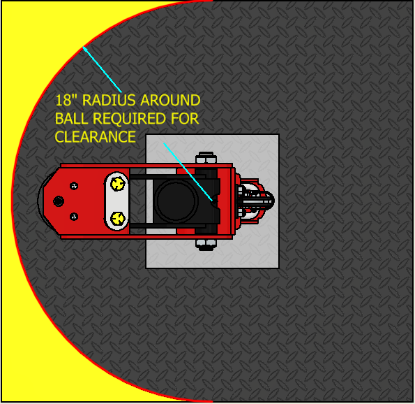
- Turning Clearance: Confirm there is an 18″ clear radius around the ball to prevent the hitch from contacting items in the truck bed during turns.
Gooseneck Balls We Recommend
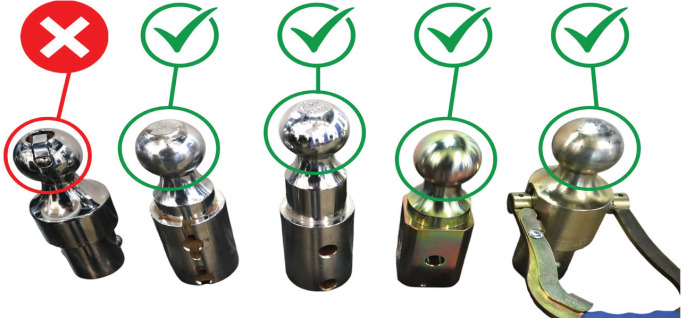
Recommended: We highly recommend using gooseneck hitch balls that are completely spherical or have a flat top. This is to ensure the coupler lasts as long as possible.
Not Recommended: We strongly advise against using a Puck/Pop-In style ball due to the sharp edges of the clip grinding on the inside of the coupler, which reduces the life of your coupler.
Common Replacement Parts
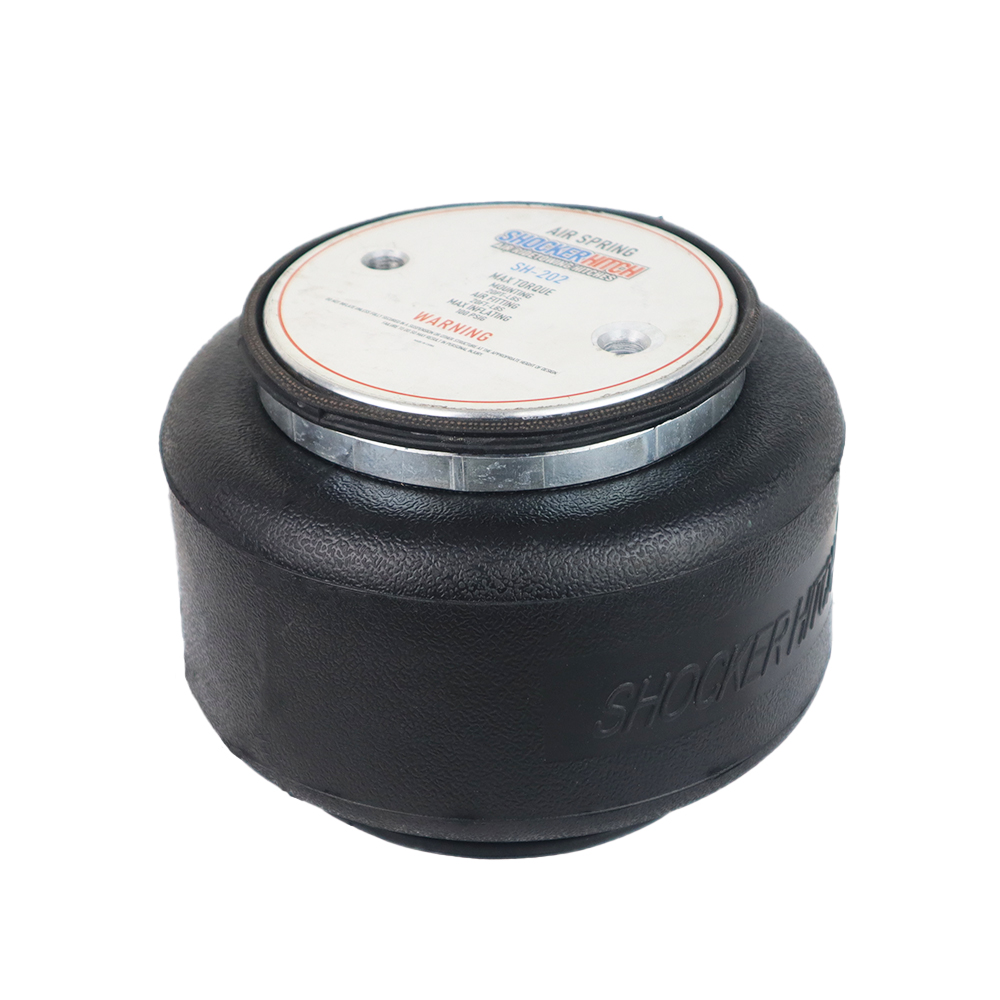
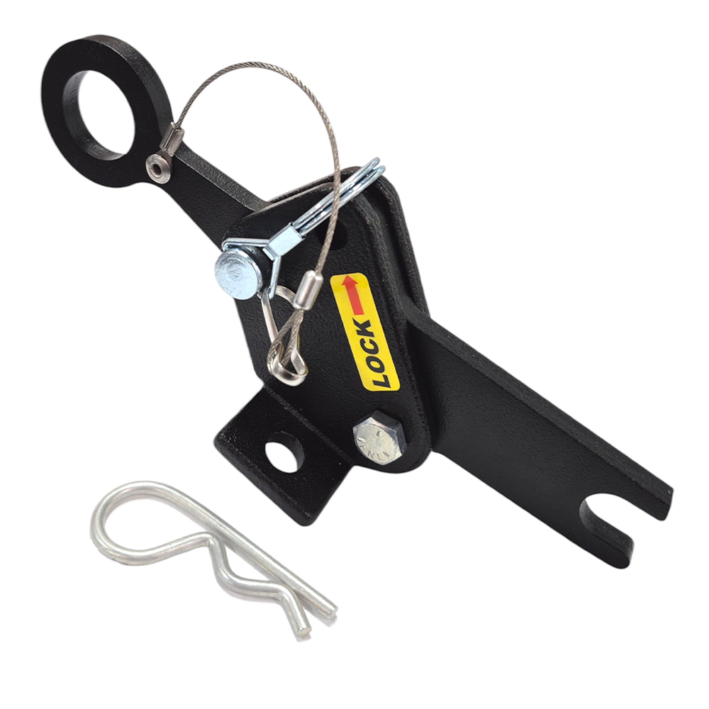
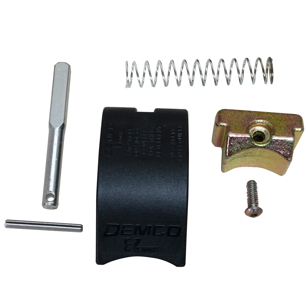

FAQ
- Best Gooseneck Ball for Longer Coupler Life
- Why Grease Your Hitch Ball?
- How to Back Up a Gooseneck Trailer?
- What is the Benefit of an Air Hitch?
- Understanding Towing Capacity
Safety Notice: Towing capacity is limited by the lowest rated component. Do NOT exceed Gross Vehicle Weight Rating or Shocker Hitch weight ratings. The Quick Air® pin box is ONLY rated for 24,000 LBS GTW and 6,000 LBS TW. Any modification to the hitch or pin box voids warranty and is done so at your own risk. Manufactured by Shocker Hitch® USA in Jamestown, ND.
We’re here to help. Contact Us